| Nominal Outside Diameter (Inch) D +0.0000 -0.0005 | Catalog Number | Load Capacity – (Pounds) Load At Center of “A” |  | Torsional Spring Rate See Note (2)
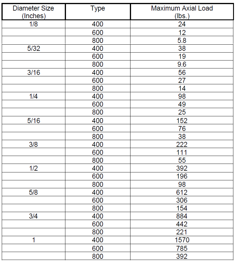
in – lb Degree | Maximum Axial Load (lbs.) | ||
| See Note (1) | |||||||
Series 5000 Cantilevered (size-type) | Vc | Vt | L ±0.003 | A ±0.005 | |||
| 0.1250 | 5004-400 | 25.5 | 25.5 | 0.200 | 0.095 | 0.0140 | 24 |
| 5004-600 | 8.9 | 13.0 | 0.0017 | 12 | |||
| 5004-800 | 1.0 | 3.7 | 0.0002 | 5.8 | |||
| 0.1562 | 5005-400 | 39.5 | 39.5 | 0.250 | 0.120 | 0.0279 | 38 |
| 5005-600 | 13.8 | 20.0 | 0.0035 | 19 | |||
| 5005-800 | 1.5 | 6.0 | 0.0004 | 9.6 | |||
| 0.1875 | 5006-400 | 56.0 | 56.0 | 0.300 | 0.142 | 0.0473 | 56 |
| 5006-600 | 19.8 | 28.0 | 0.0057 | 27 | |||
| 5006-660 | 12.2 | 20.2 | 0.0037 | 27 | |||
| 5006-800 | 2.1 | 8.0 | 0.0007 | 14 | |||
| 0.2500 | 5008-400 | 101.0 | 101.0 | 0.400 | 0.190 | 0.1141 | 98 |
| 5008-600 | 35.5 | 51.0 | 0.0143 | 49 | |||
| 5008-800 | 3.7 | 14.5 | 0.0018 | 25 | |||
| 0.3125 | 5010-400 | 158.0 | 158.0 | 0.500 | 0.238 | 0.2234 | 152 |
| 5010-600 | 55.0 | 79.0 | 0.0286 | 76 | |||
| 5010-800 | 5.8 | 23.0 | 0.0036 | 38 | |||
| 0.3750 | 5012-400 | 228.0 | 228.0 | 0.600 | 0.285 | 0.3840 | 222 |
| 5012-600 | 80.0 | 114.0 | 0.0480 | 111 | |||
| 5012-800 | 8.4 | 32.8 | 0.0058 | 55 | |||
| 0.5000 | 5016-400 | 403.0 | 403.0 | 0.800 | 0.380 | 0.9080 | 392 |
| 5016-600 | 141.0 | 202.0 | 0.1134 | 196 | |||
| 5016-800 | 14.6 | 58.0 | 0.0142 | 98 | |||
| 0.6250 | 5020-400 | 634.0 | 634.0 | 1.000 | 0.475 | 1.8500 | 612 |
| 5020-600 | 222.0 | 317.0 | 0.2321 | 306 | |||
| 5020-800 | 23.0 | 93.0 | 0.0295 | 154 | |||
| 0.7500 | 5024-400 | 910.0 | 910.0 | 1.200 | 0.570 | 3.1800 | 884 |
| 5024-600 | 318.0 | 455.0 | 0.3980 | 442 | |||
| 5024-800 | 33.0 | 130.0 | 0.0500 | 221 | |||
| 1.0000 | 5032-400 | 1620.0 | 1620.0 | 1.600 | 0.770 | 7.5200 | 1570 |
| 5032-600 | 567.0 | 815.0 | 0.9390 | 785 | |||
| 5032-800 | 60.0 | 236.0 | 0.1175 | 392 | |||